Overview
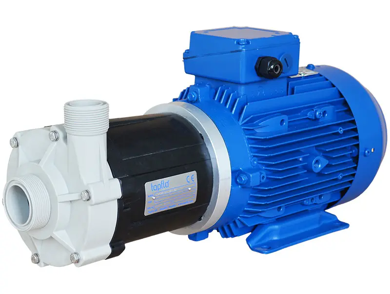
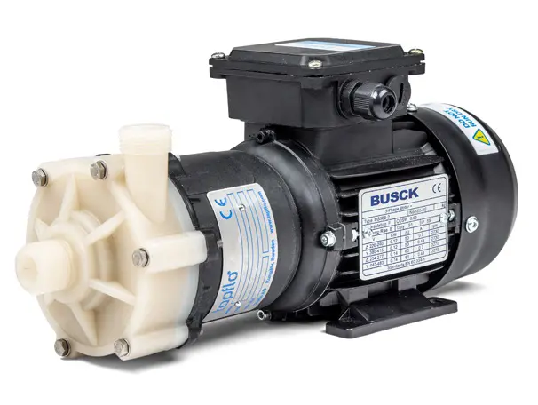
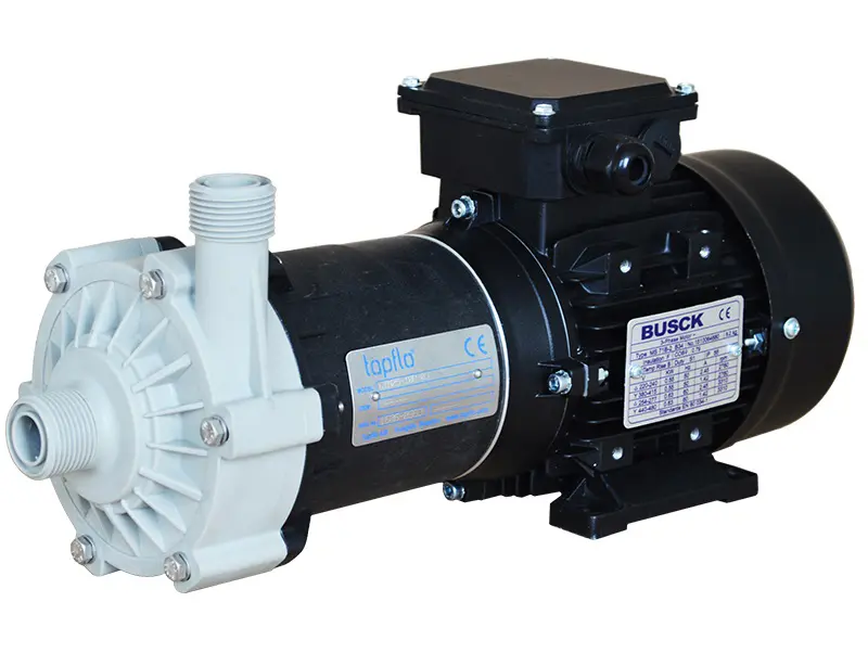
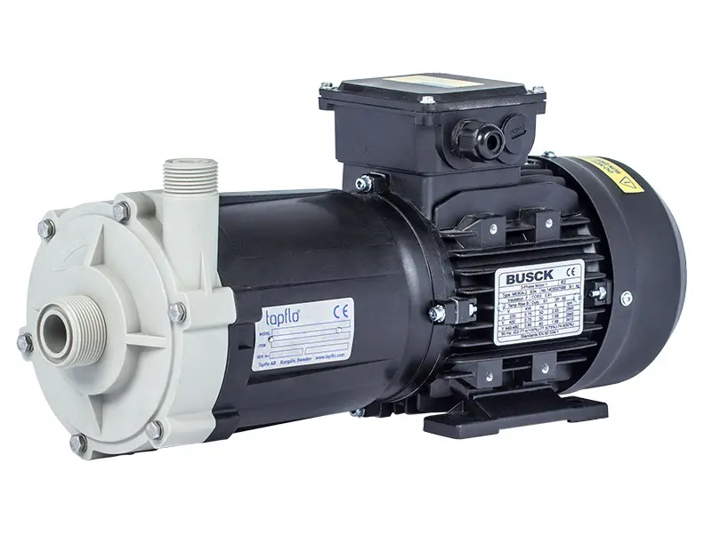
CTM pumps are used in most industries where liquids are pumped. The pumps handle many types of low and normal viscous clean liquids such as chemical aggressive and toxic.
Typical applications
Industry |
Example of application |
Chemical stockists |
Transfer of various chemicals from storage tanks to smaller containers |
Surface treatment |
Transfer, filtering and circulation of surface treatment baths |
Food and beverage |
Pumping of CIP detergent used for cleaning of pipes and other food process equipment |
Water treatment |
Dosing of acids and alkalis used as cleaning chemicals in nanofiltration |
Chemical manufacture |
Pumping of chemicals in industrial detergent equipment |
Demineralizing |
Demi-water circulation and transfer in many industrial applications |
Photo processing |
Transfer of photo develop chemicals and inclusion in processing machines |
Liquid crystal manufacture |
Pumping of concentrated acids and alkalis |
Material of components
Component |
Material/Info |
Pump casing and isolation shell (rear casing) |
PP (GF 30 %) or PVDF |
Impeller |
PP or PVDF |
Lantern (not wetted) |
PP (GF 30 %) |
Static bushings |
Ceramic (standard) or SiC |
Rotation bushings |
Charbographite (standard) or SiC |
O-rings |
FXM (standard), EPDM orFFKM Kaflon |
Magnets |
NdFeB |
Technical data
MODEL
|
CTM20-7
|
CTM25-8
|
CTM25-10
|
CTM32-12.5
|
CTM40-12.5
|
CTM50-12.5
|
A
|
70
|
90
|
100
|
105
|
105
|
110
|
2.76
|
3.54
|
3.94
|
4.13
|
4.13
|
4.33
|
B
|
48
|
58.50
|
63
|
56
|
56.5
|
54
|
1.89
|
2.30
|
2.48
|
2.20
|
2.22
|
2.13
|
C
|
93.5
|
100.5
|
136.5
|
164
|
165
|
189
|
3.68
|
3.96
|
5.37
|
6.46
|
6.50
|
7.44
|
ØE
|
15
|
18
|
18
|
15
|
23
|
30.8
|
0.59
|
0.71
|
0.71
|
0.59
|
0.91
|
1.21
|
ØF
|
15
|
18
|
18
|
23
|
30.5
|
42
|
0.59
|
0.71
|
0.71
|
0.91
|
1.20
|
1.65
|
G
|
¾”
|
1”
|
1”
|
1 ¼”
|
1 ½”
|
2”
|
¾
|
1
|
1
|
1 ¼
|
1 ½
|
2
|
H
|
¾”
|
1”
|
1”
|
1”
|
1 ¼”
|
1 ½”
|
¾
|
1
|
1
|
1
|
1 ¼
|
1 ½
|
L
|
248.5
|
279
|
334.5
|
374.5
|
402.5
|
446
|
453
|
9.78
|
10.98
|
13.17
|
14.74
|
15.85
|
17.56
|
17.83
|
M
|
36
|
40
|
45
|
54.5
|
56
|
63
|
70
|
1.42
|
1.57
|
1.77
|
2.15
|
2.20
|
2.48
|
2.76
|
N*
|
71
|
80
|
80
|
100
|
125
|
140
|
2.80
|
3.15
|
3.15
|
3,94
|
4.92
|
5.51
|
P*
|
9
|
10
|
10
|
13
|
14
|
15
|
0.22
|
0.28
|
0.28
|
0.51
|
0.55
|
0.59
|
Q
|
56
|
63
|
71
|
80
|
90
|
100
|
112
|
2.20
|
2.48
|
2.80
|
3.15
|
3.54
|
3.94
|
4.41
|
R
|
35
|
39.5
|
43.5
|
58.5
|
58.5
|
52
|
1.38
|
1.56
|
1.71
|
2.30
|
2.30
|
2.05
|
S*
|
90
|
100
|
112
|
125
|
140
|
160
|
190
|
3.54
|
3.94
|
4.41
|
4.92
|
5.51
|
6.30
|
7.48
|
T
|
112
|
126
|
141
|
160
|
170
|
200
|
230
|
4.41
|
4.96
|
5.55
|
6.30
|
6.69
|
7.87
|
9.06
|
U*
|
5,5
|
7
|
7
|
10
|
10
|
12
|
0.22
|
0.28
|
0.28
|
0.39
|
0.39
|
0.47
|
MOTOR
|
POWER
|
0.12 kW
|
0.25 kW
|
0.55 kW
|
0.75 kW
|
0.75 kW
|
1.1 kW
|
1.5 kW
|
2.2 kW
|
3.0 kW
|
4.0 kW
|
SIZE
|
56
|
63
|
71
|
71
|
80
|
80
|
90
|
90
|
100
|
112
|
WEIGHT PP [kg]
|
4.3
|
5.7
|
8.75
|
9
|
11.7
|
15.7
|
24
|
25.5
|
31.55
|
-
|
WEIGHT PVDF
|
4.45
|
5.9
|
9.2
|
9.4
|
12.2
|
16.2
|
24.65
|
26.2
|
32.15
|
-
|
OPTIONAL CONNECTIONS
|
FLANGE
|
-
|
DN25
|
DN25
|
DN32 / DN25
|
DN40 / DN32
|
DN50 / DN40
|
HOSE
|
-
|
Ø25
|
Ø25
|
Ø32 / Ø25
|
Ø40 / Ø32
|
Ø50 / Ø40
|
General characteristics
Motor
|
IEC standard, 3x400 VAC (other on request), 2900 rpm,
IP55, B34 frame
|
Pressure rating
|
CTM20:
PP pumps: PN4 at 20°C, PN2 at 70°C PVDF pumps: PN4 at 20°C, PN2 at 80°C CTM25, CTM32, CTM40 and CTM50:
PP pumps: PN6 at 20°C; PN2 at 70°C
PVDF pumps: PN6 at 20°C; PN2 at 90°C
|
Temperature
|
PP pumps: 0°C - 70°C
PVDF pumps: 0°C - 80°C (CTM20);
0°C - 90°C (CTM25, 32, 40, 50)
|
Kinematic viscosity
|
200 cSt (max)
|
Dynamic viscosity
|
10 cP (max)
|
Key components
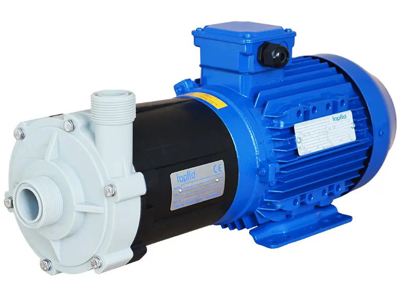
CTM is a close coupled compact pump ideal for service in little spaces like in OEM installations.
Non-metallic pumps
The wetted components are non-metallic injection moulded thermoplastics enabling excellent corrosion resistance.
The version in PP-GF (glass fibre reinforced polypropylene) provides great mechanical strength and allows liquid temperatures up to 70°C.
The PVDF (PolyVinylidine DiFluoride) version has the superior chemical resistance and allows temperatures up to 80°C.
The reliable design without shaft
The impeller magnet assembly is designed with very powerful bushings where a conventional crack sensitive shaft is not needed. This results in a pump that has fewer parts and is very reliable in service.
Excellent performance with magnet cage system
Our magnets in NdFeB (Neodymium-iron-boron) with our patent pending magnet cage system have a superior strength also under demanding circumstances. The power from the drive is transmitted even at high temperatures and with high specific gravity liquids.
1. Pump casing
2. Impeller (with magnet)
3. External magnet (drive)
4. Isolation shell (rear casing)
5. Static bushing
6. Rotating bushing
The magnet cage system
Working principle
How they work
The power from the motor is transmitted to the centrifugal impeller by means of a magnetic coupling. A so called isolation shell between the drive magnet and the impeller magnet separate the liquid side from the drive.
Working principle
1) Drive magnet, connected to the motor
2) Isolation shell (rear housing) separating the liquid side from the atmosphere
3) Impeller magnet assembly, driven by the drive magnet
Certificates
FDA §21 CFR 177 materials
FDA (U.S. Food and Drug Administration) §21 CFR 177 lists polymers, e.g. rubber and plastic materials approved for equipment in contact with food products.
EN 10204 material traceability
The EN 10204 norm gives you a checklist and traceability of materials used in the equipment. 2.1 is a general statement of compliance with material specifications, while 3.1 provides specific track records all the way to the steel mill batch (normally only on metals in contact with the product).
CE conformance
A product classified as machinery that carries the CE mark fulfill the essential health and safety requirements of the EC Machinery Directive 2006/42/EEC.
ATEX Directive 94/9/EC
Equipment intended and approved for safe operation in potentially explosive atmospheres. The equipment is divided in main groups, categories, apparatus groups and temperature classes to define its suitability in the actual zone.